Shaft Press Fit Tolerance Chart

Too Tight Or Perfect Fit When To Use Press Fits In Your

Engineering Tolerance Wikiwand
Downloads Kiraly Tool And Die Inc
Engineer Toolbox Tolerance Calculator Gmn Bearing Usa

Fit Calculator That Fits
Http Books Library Online Files Elebda3 Net Gh 235 Pdf
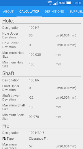
Fit Tolerance Iso Apps On Google Play
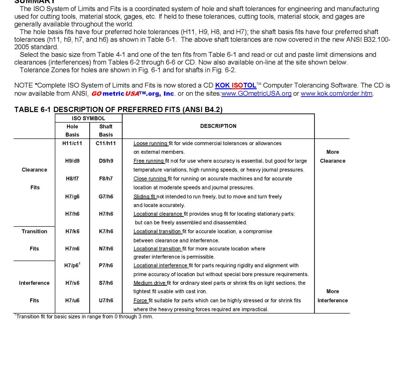
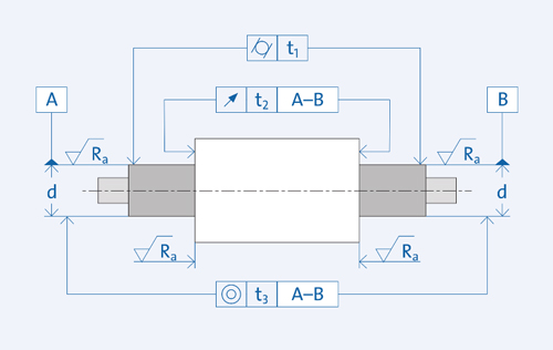
5 shaft and housing fits.

Shaft press fit tolerance chart. According to nominal size and fit type selection among running and sliding rc locational clearance lc locational transition lt locational interference ln force and shrink fn fits size limits for holeshaft are calculated with schematic representation of the fit. Whenever possible selection of tolerance class shall be done among these tolerances to avoid too many numbers of tools and gauges. Shaft and housing fits normal tolerances chamfer dimensions radial internal clearance axial internal clearance reduction in radial internal clearance fag rolling bearing greases arcanol chemicalphysical data guidelines for use. Ansi limits and fits calculator works in line with ansi b41 standard which is based on inch units.
Conversely an interference fit is a fit where there will always be overlap in the joint between the specified mating shafthole even at the minimum material condition values allowed by the shaft and maximum value allowed by the hole tolerance values ie the largest hole and the smallest shaft. 9 normal tolerances normal tolerances for fag. Interference press shrink fit calculator. 4 mh 1 medias schaeffler technologies page tables dimension and tolerance symbols.
Simply bearings ltd providing iso limits and fits for your bearing and bushing needs. Mechanical tolerance standards charts geometric boundaries ii gdt reference book. This concept is illustrated in the figure below for both clearance and interference fits. The size ranges given are for typical size ranges utilized within industry.
